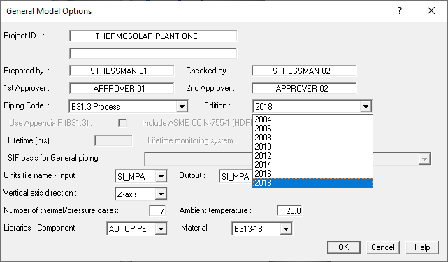
AutoPIPE contains all revisions of the EN 13480 standard and numerous revisions to the B31.1 and B31.3. Most plants designed under ASME use B31.1 for the water and steam pipes and B31.3 for the HTF, Molten Salts and service pipes.
Always up to date, AutoPIPE offers the latest version of the code that you require and lets you choose the version that your project needs. To update a calculation, just change the year of the norm and AutoPIPE will update the materials and stress formulas to that year. See+
Using the closing time of the turbine inlet valve, the flow rate and the steam's conditions, AutoPIPE calculates the magnitude of the water hammer wave depending on the length of each straight section, and prepares the Time History considering all directional changes.
In this way, you will not have to apply the maximum load (DLF = 2) simultaneously on all elbows, but carry out the integration of forces with their real magnitude following the pace of the wave. And you can apply the wave in the branches until the first closed valve and at the precise moment.
Reduce man hours while increasing precision with AutoPIPE.
AutoPIPE allows you to insert structure models into the piping model, to connect the supports to the structure and perform the combined calculation.
When executing the combined calculation, the stiffness of the supports is no longer infinite, but is the real one provided by the support structure.
The dynamic analyzes performed will use the vibration modes and mass of the combined model. With what they will be much more real than another calculation approach.
The connection of the supports to the structure is fast and automatic.
Once the stress calculation has been performed, the piping model can be imported into the STAAD.Pro model and the calculated loads used in the structure calculation. Which saves hours of load introduction work.
The user can keep open as many windows of AutoPIPE as he needs with one license. Thanks to that you can

Load Sequence: Steam lines are heated up to the operating temperature while the condensate is drained, and then pressure is applied to the line. So, the load sequence used by AutoPIPE is:
Weight Temperature Pressure
This sequence do not match with the sequence used in chemical plants, where pressure is applied before temperature. In this case AutoPIPE Sequence is:
Weight Pressure Temperature
This methodology is the one recommended by ASME and ensure the proper calculation of the stress. In the first sequence the gaps are closed due to the temperature, but in the second sequence are closed due to the pressure extension of the pipe. Many programs can only deal with the second one. See+
The equipment's are included directly in the stress model, no external routines are needed, so when executing the stress calculation, the equipment report can be requested immediately.
In AutoPIPE the user can add weight at any point on the pipe, both centered and with an offset, in order to include the weight of instruments, reinforcements, trunnions, etc. And in this way make a more accurate mass model for both static and dynamic analysis.
The valves include fields to add the weight and the location of the actuator's center of gravity, so no additional elements are required.
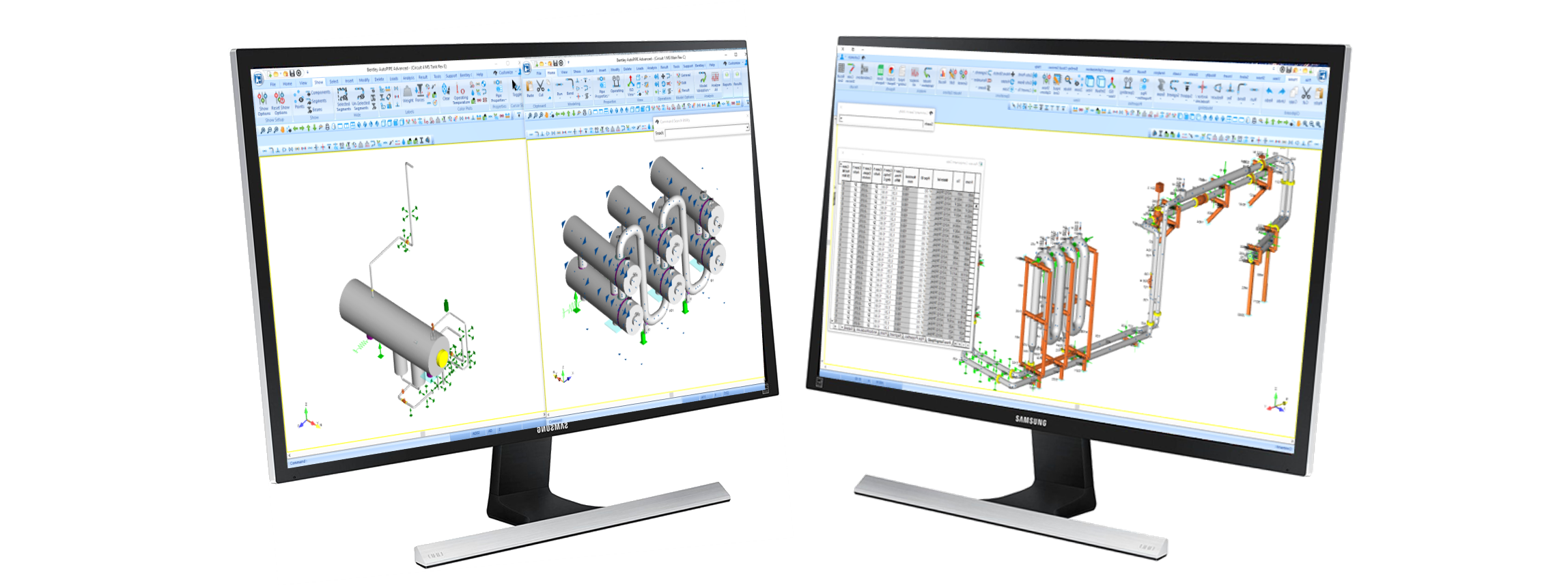
In the image below you can see the blue arrows that indicate that additional weight has been placed at that point. You can also see the actuators of the control or motorized valves.
Calculating the correct weight for a piping system can save a lot of headache in the field during commissioning and operation.
All supports have a field for the weight of the support, which has to be considered in the analysis since it is fixed to the pipe.
The supports also include a field for the support Tag.
Dampers in AutoPIPE are placed like any other support without the need to indicate any displacement imposed on the anchor point, and the program activates them only in the event of an earthquake and water hammer.
The user can also activate them for wind, since fast gusts make dampers be activate.