
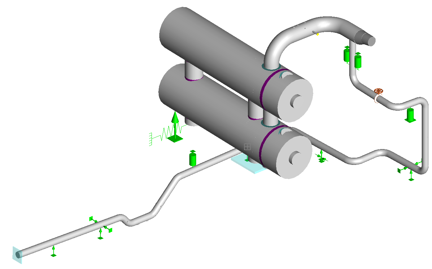
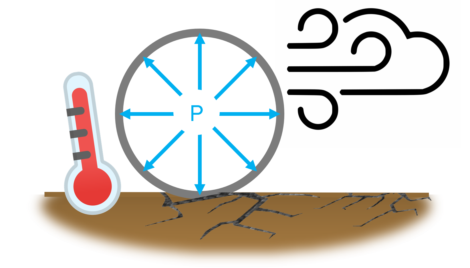
The Support Optimizer allows you to speed and improve your calculations based on:
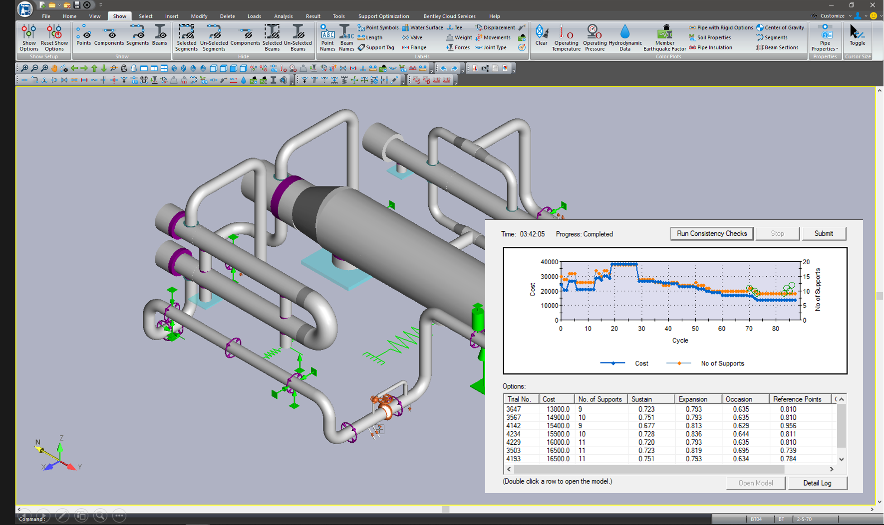
Calculate the best support options that meet all these requirements and at the lowest cost. The Support Optimizer uses Artificial Intelligence with Genetic Algorithm to run thousands of options and find the cheapest one that meets the specifications.
The Support Optimizer can be used to improve stress calculations that we have solved, but want to reduce the cost, or for new systems. It runs in the background, so it allows us to continue working on other calculations at the same time. See+
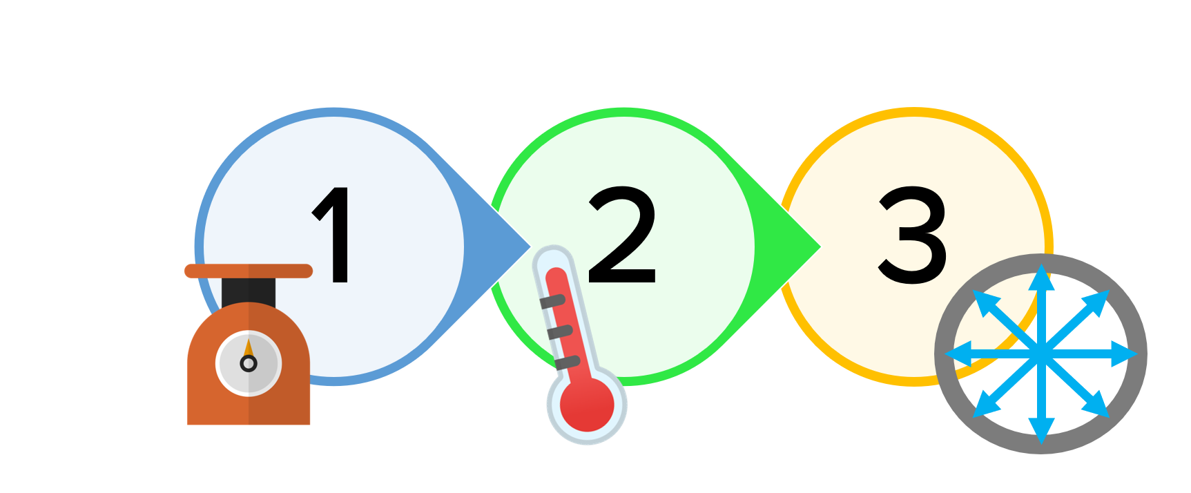
As a general rule, in the Oil industry the start-up sequence is first pressurize the line and then go to the operating temperature. In AutoPIPE the sequence is:
Weight Pressure Temperature
In LNG plants and other chemical plants as the Olefins units the pipe has to be cold down slowly up to a cryogenic temperature and then is pressurized. In AutoPIPE the sequence is:
Weight Temperature Pressure
This methodology is the one recommended by ASME and ensure the proper calculation of the stress. In the first sequence the gaps are closed due to the pressure extension of the pipe, but in the second sequence are closed due to the temperature. Many programs can only deal with the second one.
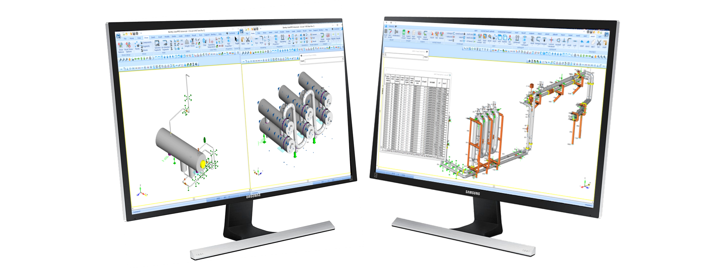
The user can keep open as many windows of AutoPIPE as he needs with one license. Thanks to that you can
Multiple sessions run on one computer only require one license.
AutoPIPE has multiple editions of the standards, not only of the stress formulas, the program also has the material libraries to be able to replicate old calculations:
| Standards | Years |
| B31.1 | 2018, 2016, 2014,2012, 2010, 2009, 2007… til 1967 |
| B31.3 | 2018, 2016,2014, 2010, 2008, 2006 and 2004 |
| EN 13480 | 2017, 2012, 2010 and 2002 |
| B31.4 | 2016, 2012, 2009 and 2006 |
| B31.8 | 2016,2014, 2012, 2010, 2007 AND 2003 |
There are many other codes available.
The equipment's are included directly in the stress model, no external routines are needed, so when executing the stress calculation, the equipment report can be requested immediately.
In AutoPIPE the user can add weight at any point on the pipe, both centered and with an offset, in order to include the weight of instruments, reinforcements, trunnions, etc. And in this way make a more accurate mass model for both static and dynamic analysis.
The valves include fields to add the weight and the location of the actuator's center of gravity, so no additional elements are required.
In the image below you can see the blue arrows that indicate that additional weight has been placed at that point. You can also see the actuators of the control or motorized valves.
Calculating the correct weight for a piping system can save a lot of headache in the field during commissioning and operation.
All supports have a field for the weight of the support, which has to be considered in the analysis since it is fixed to the pipe.
The supports also include a field for the support Tag.
Dampers in AutoPIPE are placed like any other support without the need to indicate any displacement imposed on the anchor point, and the program activates them only in the event of an earthquake and water hammer.
The user can also activate them for wind, since fast gusts make dampers be activate.